© www.white-coppice.co.uk 2022
History
It all started in 1850 when John Bateman designed and built Chorley Reservoir (later called High Bullough Reservoir by some). This was built to provide the population of Chorley with good clean drinking water. Within the next 10 years 7 further reservoirs were built and designed by Thomas Hawksley for Liverpool Water Company, who also took responsibility for Chorley’s water supply. At that time these were state of the art reservoirs and Hawksley’s system included pressure in the pipes For more info about Thomas Hawksley click this link THOMAS HAWKSLEYThe Chain
Shortly after Chorley Reservoir was built, the reservoirs of Anglezarke, Rivington Upper and Lower, were added to the scheme. These were connected by a 3.5 mile canal (named The Goit or Goyt) to three further reservoirs at Abbey Village, near Chorley, namely Rakes and Upper and Lower Roddlesworth None of the reservoirs are particularly deep - Anglezarke averages 28ft deep with much of it being no more than 12 - 15 ft deep at the Heapey end. At least two of the reservoirs had long arched footbridges over the overflows, enabling Waterboard employees to cross them with ease. Iron supports were bolted on to the huge slabs of stone that formed the lip of the overflow. On top of these supports, thick wooden planks were secured to the them and a handrail above the planks provided safety for the workers to cross. The two I know of were at the top of the Yarrow overflow (see pics) and across the wide overflow from Lower Roddlesworth to RakeToday
Although there is still an overflow from Chorley Reservoir it is technically disconnected from the chain. Its location is stunning and difficult to see as it is almost surrounded by hills. The rest of the chain remains in tact, though the Roddlesworth reservoirs seem to be “dormant“, ie their valve aren’t altered when shortages occur in other reservoirs down the chain. When built the Goit was 21 feet wide. It was well maintained and kept free of silt build up. In places today it is choked up and down to around 5 ft width in places.From the past
The following extract was written in 1904. Most of the detail was extracted from the first part of the "Report of the Water Engineer of the Liverpool Waterworks" which was published in1900 EARLY in the nineteenth century the utterly inadequate character of the water supply of the growing town of Liverpool was engaging the attention of the Town Council, and numerous schemes were suggested for meeting the difficulty. As a result of a prolonged agitation for a better supply, the Council in 1846 engaged three engineers—Mr. Hawksley, Mr. Cubitt, and Mr. Rendel—to investigate and report upon the various schemes that were proposed. Suggestions to draw the water supply from Bala Lake, the River Alt, and other sources, were discarded, and a scheme prepared by Mr. Hawksley, afterwards known as the Rivington Pike scheme, was adopted. Mr. Hawksley proposed to impound the waters of the rivers Douglas and Roddlesworth, and form a reservoir in the valley between Rivington Pike and Heath Charnock. In the following year the Corporation obtained the necessary Parliamentary powers, but there was an active minority in Liverpool very much against the scheme, and strenuous opposition was offered to the carrying out of the work by those who considered that wells sunk in the sandstone rock within or close to the Borough would afford an ample supply of water. The result was that the work of construction was delayed, and although the Act of Parliament was obtained in the year 1847 it was not until August 1857 that the water from Rivington was first delivered in Liverpool. It is curious to hear that when Rivington water was first supplied to the consumers, the greatest dissatisfaction was expressed on account of its brown colour, due to the presence of peat and the decomposition of vegetable organic matters left in the valleys forming the sides and bottoms of the reservoirs. These difficulties were eventually overcome, and the new supply delivered in unexceptionable condition in the matter of colour as well as in other respects, to the general satisfaction of the people of Liverpool; and it is said that they grew so accustomed to the bright Rivington water, derived from the millstone grit formation, that when forty years later the water from Vrynwy was first delivered many of the consumers complained of its insipidness and brown colour. In 1860 the growth of the population of Liverpool and the increasing demand for water rendered necessary the construction of a new reservoir on the River Roddlesworth at Tockholes, six miles to the north of Rivington village. This reservoir afforded additional storage to impound the rainfall of wet years, but did not add to the area of the watershed. It was found in 1867 that further supplies were again needed, and the compensation water, which had hitherto been discharged into the River Roddlesworth, was purchased, and power obtained to construct another reservoir at Rivington in the Yarrow Valley, to the east of Anglezarke, and two new filter-beds. This work was begun in 1868, and finished in August 1875, and the new reservoir filled with water in February 1877. The Rivington watershed comprises about 10,000 acres of land, and the elevation ranges from 450 to 1500 feet. The principal streams that supply the water, as already stated, are the Roddlesworth, Rake, Yarrow, and Douglas, and the rainfall is collected into reservoirs formed by earth embankments carried across the natural valleys. The area and contents of each reservoir and the principal dimensions of the embankments are given in the subjoined table. Name of Reservoir Area in Acres Contents in Embankment Embankment millions of length in feet greatest depth gallons - in feet Roddlesworth Upper 26 178.0 1190 69 Roddlesworth Lower 16.4 99.7 590 81 Rake 13.8 79.9 1500 84 Anglezarke 191.6 1019.0 3550 46 Chorley 10.1 48.3 990 39 Rivington (Upper & Lower) 275 1841.0 6280 61 Yarrow 65.0 839.2 2894 103 Filter-beds 5.82 - - - Roddlesworth and Rake-brook reservoirs are connected with the Anglezarke by a canal 3.5 miles long and 21 feet wide. The total surface area at the overflow level is 598 acres, and their total length measured along the top water lines is 5.5 miles. The length of the combined embankments is over 3 miles. The highest embankment is that of the Yarrow reservoir, which is 103 feet above the bottom of the valley. The deepest puddle trench is also at this reservoir. Here the trench had to be carried down to a depth of 167 feet below the natural surface before a solid foundation could be obtained; the total height from the bottom of the foundation to the top of the dam being 257 feet. A description of the method of construction adopted at the Yarrow Reservoir will apply, practically, to all the Rivington Reservoirs. A suitable site for the embankment having been selected, a trench was excavated on the centre line of the intended work and carried down to the solid rock right across the valley. This was filled with clay deposited in layers of 9 inches, and carefully puddled so as to produce a homogeneous watertight material. This clay wall, having reached the natural surface of the ground, was continued through the embankment, which was also built in thin layers thoroughly rammed and consolidated on both sides of the clay centre. Before commencing the erection of the embankment all peat and unsound material were stripped from the site. The inner or water slopes of the embankment have been built to an angle of 3 to 1, and outer slopes to an angle of 2 to 1.The impermeability of the dam depends upon the wall of puddled clay in the heart of the dam tied into the solid rock at the bottom and sides of the valley. The clay wall has been carried up to a batter on each side of 1 inch to every foot vertical, the thickness at the top being 6 feet. The inner slopes of the bank are protected by 15 inch pitching, consisting of the millstone grit of the neighbourhood, laid on a bed of broken stone. The outer slopes have been soiled and grassed over. The outlet from the Yarrow Reservoir is by a tunnel driven through the rock at the side of the valley, and not through the embankment itself as in the earlier reservoirs. The tunnel and valve shaft are both lined with blue bricks. The bye-wash or overflow is 100 feet wide. The weir and apron and steps are formed of heavy ashlar closely jointed. The pitching forming the bye-wash is of millstone grit, neatly dressed and soundly laid on asphalt concrete. The wing walls are of squared rubble, neatly and closely laid.All the reservoir embankments and tunnel outlets at Rivington are sound and watertight, and their excellent condition to-day is evidence of the skill and care exerted in their construction. The waste weirs or bye-washes have proved to be of ample capacity for dealing with the largest floods that have been experienced. All the water for the supply of Liverpool has to pass into and through the Lower Rivington Reservoir. From this reservoir the water is drawn off for filtration through sand filters. The original filtration works consisted of six beds, having a total area at the surface of the sand of 182,982 square feet, and two open filtered water tanks, capable of holding 8,384,000 gallons. In 1870—75 two additional filter-beds were constructed. The area of these two beds is 71,302 square feet, making the total filtering area of the eight beds 254,284 square feet. The filtering material consists of 2 feet 6 inches of sand laid on the top of layers of gravel varying in size from 4 inches diameter to 1/8 inch diameter. The average rate of filtration per acre of sand is 2,240,920 gallons per day, or 81 cubic feet per square foot per day.The Rivington Reservoirs
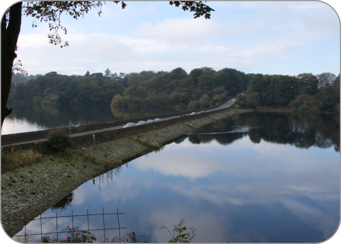
A miniature Lake District and beautiful it is too.


The Drought of
1949, a link to
British Pathe.
Click the icon to
watch the video


The Drought of
1949, a link to
British Pathe.
There is no sound
on this video.
Some images are
of Ladybower, but
most are Rivington